This chapter provides an introduction to:
Each of the following TruCluster Software Products:
TruCluster Available Server Software (Available Server, AS)
TruCluster Production Server Software (Production Server, PS)
TruCluster MEMORY CHANNEL Software (MEMORY CHANNEL, MC)
The concept of using an available server environment (ASE) to provide highly available services and storage. An Available Server configuration consists of one ASE. A Production Server configuration must contain one ASE, and may contain up to four ASEs. A MEMORY CHANNEL configuration contains no ASEs.
Hardware configuration concepts
The following chapters describe how to set up and maintain Production Server, Available Server, and MEMORY CHANNEL hardware configurations. See the TruCluster Software Products Software Installation manual for information about software installation, and the TruCluster Software Products Administration manual for detailed information about setting up member systems and services.
The DIGITAL UNIX TruCluster Software Products Version 1.5 suite of products allows multiple systems to be clustered as a single computing resource. The TruCluster product suite contains three products, as follows:
TruCluster Available Server Software--The TruCluster Available Server Software (formerly known as DECsafe Available Server) significantly reduces down time due to hardware and software failures. Cluster activities are coordinated within an available server environment (ASE), an integrated organization of systems and external disks connected to shared SCSI buses that together provide highly available software and disk data to other systems.
TruCluster MEMORY CHANNEL Software--The TruCluster MEMORY CHANNEL Software is an enabler for highly optimized applications that require high performance data delivery over the PCI-based MEMORY CHANNEL interconnect. The MEMORY CHANNEL application programming interface (API) library provides APIs for MEMORY CHANNEL data channel and locking functions.
TruCluster Production Server Software--The TruCluster Production Server Software (formerly known as TruCluster Software) combines the capabilities of the TruCluster Available Server Software and TruCluster MEMORY CHANNEL Software to provide a high-performance, highly available, and scalable operating environment.
The TruCluster Production Server Software allows the processing components of an application to concurrently access raw devices, supporting highly parallelized database applications such as Oracle Parallel ServerTM (OPS).
The TruCluster Production Server Software distributed lock manager (DLM) synchronizes access to the resources that are shared among cooperating processes throughout the cluster. DLM provides services to applications to enforce a resource-sharing policy based on mutual exclusion or restricted sharing, plus services that notify the process that owns a resource that is blocking another resource requesting the resource. DLM allows an application to synchronize clusterwide access to shared resources, ensuring data integrity.
The distributed raw disk (DRD) service allows a disk-based, user-level application to run within the cluster, regardless of where in the cluster the physical storage it depends upon is located. A DRD service allows applications such as distributed database systems or transaction processing systems (TPSs) parallel access to storage media from multiple cluster member systems
Each of the products in the TruCluster product suite provides a different aspect of TruCluster functionality. While the TruCluster Production Server Software offers the benefits of all three products, the TruCluster Available Server Software and the TruCluster MEMORY CHANNEL Software can also be used as standalone products in situations where only partial TruCluster functionality is required.
Many applications, such as database applications and system services (for example, exported file systems and mail), are critical to business operations. Therefore, it is desirable to provide consistent and uninterrupted access to software or data on disks in a network environment. However, software or data on disks can become unavailable due to scheduled or unscheduled downtime for the system that is providing the resources. For example:
System management operations such as maintenance, installations, and backups can prevent a system from providing data and applications.
System crashes, although infrequent, interrupt network access to the disks and applications that the crashed system served.
Network and I/O failures make data and applications unavailable.
An available server environment (ASE) is an integrated organization of systems and disks located on a shared SCSI bus that together provide highly available software and data to client systems. An ASE makes applications and data highly available, and can significantly reduce down time due to hardware and software failures.
In an ASE, the software provides multihost access to shared SCSI disks or tape and a generic failover mechanism for network-based applications and system services. In addition, the POLYCENTER Advanced File System (AdvFS), and the Logical Storage Manager (LSM) can be used within an ASE to provide fast file system recovery and high disk availability and reliability with disk mirroring.
In an ASE, you set up services for the applications or disk data that you want to make highly available. The TruCluster software failover mechanism makes applications and disk data independent of the availability of any one particular system. The applications are installed on each member system, and the disks are shared, so any member system can run an application and access data. This enables clients to have virtually uninterrupted access to resources.
When you create a service in an ASE, at a minimum, the
asemgr
utility prompts you for the following information:
A unique name
Either an application or storage configuration to make highly available
Information about which member systems you want to run the service and how you want the service to behave when a failure occurs
Only certain types of applications can be made highly available with an ASE service. The application must have the following characteristics:
The application must run on only one system at a time.
The application must be able to be started and stopped using a set of commands that are performed in a specific order. When you set up a service, these commands are included in a set of programs called action scripts. Available Server software uses action scripts to fail over the services in the ASE.
The following sections descuss the ASE environment in more detail.
TruCluster software provides support for various types of ASE services:
Network File System (NFS) service--Enables you to provide highly available access to exported disk data (for example, mounted disks or system mail). When you create an NFS service, you must specify a unique Internet Protocol (IP) host name for the service name and the UNIX file systems, Advanced File System (AdvFS) filesets, or Logical Storage Manager (LSM) volumes that you want to export.
You can also use your own action scripts in an NFS service if you want to fail over an application in addition to data. The member system that runs the service responds to the IP address that is assigned to the NFS service name and exports the service data. If the service is relocated to another member system, the new member system responds to the IP address. Clients are unaware of the change in the system that exports the data, and they experience only a temporary NFS server time out.
Disk service--Enables you to provide highly available access to disks or a disk-based application, such as a database program. A disk service is similar to an NFS service except that no data is exported. When you create a disk service, you must specify the UNIX file systems, AdvFS filesets, or LSM volumes that you want to make highly available.
You can also use your own action scripts in a disk service if you want to fail over an application in addition to data. Optionally, you can specify a unique IP host name for the service name, so that the member system that runs the service responds to the IP address. If the service is relocated to another member system, the new member system responds to the IP address.
User-defined service--Enables you to provide highly available access to an application that is not disk based (for example, a login service). You must use your own action scripts in a user-defined service to fail over the application.
Distributed raw disk (DRD) services allow a disk-based, user-level application to run within a cluster, regardless of where in the cluster the physical storage on which it depends is located. A DRD service allows an application, such as a distributed database system or transaction processing (TP) monitor, parallel access to storage media from multiple cluster members. Applications that perform I/O involving sets of large data files, random access to records within these files, and concurrent read/write data sharing can benefit from using the features of DRD. As deployed within an ASE, a DRD service can survive failures of both the server system and any mirrored disk participating in the service.
A DRD service is applicable to the TruCluster Production Server Software product only.
Tape service--The generic ASE tape service adds the capability to support NetWorker server failover with the TruCluster Production Server Software and TruCluster Available Server Software products. The tape service depends upon a set of one or more tape devices. There may be media changer devices and file systems associated with the tape devices. The service enables the user to configure the NetWorker server or other tape-based applications for failover.
A user may perform existing tape applications on tape device on a shared SCSI bus. However, the user should be aware that an ASE tape service operation or system reboot of any system in the cluster on the shared SCSI bus could cause a SCSI reset, resulting in the premature termination of the user's job.
Therefore, do not perform tape applications on tape devices on a shared SCSI bus unless you know exactly what is going on within the ASE.
Figure 1-1 shows how the services in the ASE appear to clients.
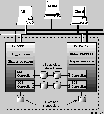
As shown in
Figure 1-1, clients use the service names
nfs_service,
dbase_service,
mail_service, and
login_service
to access the ASE services through a network.
An NFS service can use only disk data, or it can use applications and
disk data.
For example, the
nfs_service
service consists
of only NFS disk data, but the
mail_service
service consists
of NFS disk data and the
sendmail
command.
A disk service can also use only disk data, or it can use applications
and disk data.
For example, the
dbase_service
service
consists of both disk data and a database application.
A user-defined service can use only applications.
For example, the
login_service
service consists of only the
ifconfig
program.
A problem on Server 1 might cause the
nfs_service
and
dbase_service
to fail over to Server 2.
The clients
would notice a short disruption of those services, but they would once again
be available when started on Server 2.
Both the TruCluster Available Server Software and TruCluster Production Server Software consist of the daemons, scripts, user interface, and drivers necessary to provide ASE functionality. Therefore, an ASE functions pretty much the same in both products.
With the TruCluster Available Server Software product, there can be only one ASE. All the member systems must be connected to the same shared SCSI bus (or buses).
With the TruCluster Production Server Software product, there must be at least one ASE; however, there may be multiple ASEs (a maximum of four), with between two and four systems in each ASE. There can also be up to eight systems in a cluster, but cluster members do not need to be ASE members, although they must be connected to other cluster members with the MEMORY CHANNEL interconnect.
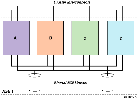
Figure 1-2 shows a four-member configuration with one ASE. Note that all four systems are connected to both shared SCSI buses. This figure can represent either an Available Server or Production Server configuration. With a Production Server configuration, the cluster interconnect is the MEMORY CHANNEL, and with the four-member system configuration shown, there would have to be a MEMORY CHANNEL hub (which is not shown).
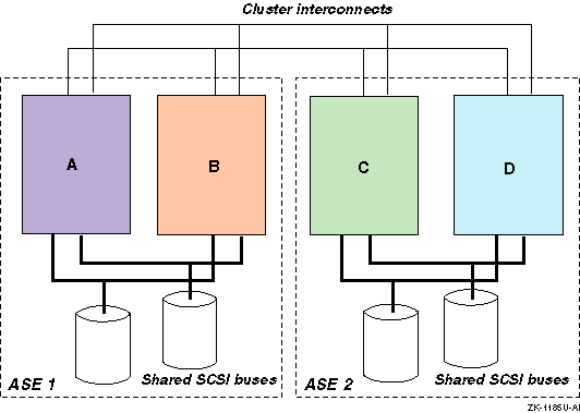
The TruCluster Production Server Software product allows multiple ASEs. Each ASE is numbered individually. All member systems in an ASE must be connected to the same shared SCSI buses. Figure 1-3 shows a four-member Production Server configuration with two ASEs. In this configuration, member systems A and B are in ASE 1 and systems C and D are in ASE 2. The cluster interconnect is the MEMORY CHANNEL and the MEMORY CHANNEL hub, which is not shown.
Before you install the TruCluster Available Server software and set up the members and ASE services, you must set up the hardware. The TruCluster Available Server hardware configuration consists of a number of highly specific hardware components needed to support an available server environment (ASE). In addition, you must adhere to a number of configuration requirements for the SCSI bus configuration and device firmware. If you fail to adhere to these requirements, ASE operation will be impaired.
The hardware components needed to support TruCluster Available Server are as follows:
Member systems--The member systems are the basic computing resources in a TruCluster Available Server configuration. The configuration can include from two to four member systems. The member systems run applications and provide access to data, and must be connected to at least one shared SCSI bus and one common network. The member systems communicate with each other and monitor the shared devices and the network through the bus and through the network. If a hardware or software failure prevents a member system from running an application or providing data, the Available Server failover mechanism relocates resources to a viable system, which provides high availability.
SCSI controllers--Each member system must have at least one supported SCSI controller installed in an I/O bus slot to connect the system to a shared bus. The use of multiple shared SCSI buses allows data to be mirrored across SCSI buses.
Shared SCSI bus--Member systems must be connected to at least one shared SCSI bus, and a storage shelf is usually connected to a shared bus. Shared SCSI buses must have the same logical number on each member system, must be properly terminated, and must be within the cable length limit. You must connect devices to a shared bus in a way that allows you to disconnect them without affecting bus operation. Eight SCSI IDs are available on each bus.
Storage configuration--Disks used in an ASE must be located in external storage expansion shelves connected to a shared SCSI bus. This enables all the member systems to access the data on the disks. Because these external units have their own power source, they are not dependent on any system's power.
Network interconnect--Member systems must be connected to at least one common Internet Protocol (IP) subnet. Available Server uses the Internet for client access and ASE daemon communication purposes.
For client access, Available Server allows you to configure up to four monitored network adapters (which must be on separate IP subnets). When a monitored network interface fails on a member, the status is passed to a script that you can customize. The default behavior of the script is to relocate all services from a member that experiences a failure of all monitored network interfaces. The services are relocated to a member system that has at least one functioning monitored interface.
Additionally, the ASE daemons communicate over the primary network
(set up by the running
asemgr
after the software has
been installed).
The primary network is monitored by default.
A backup
network may also be defined for ASE daemon communication.
A failure of
the primary network will cause ASE daemon communication to fail over to the
backup network.
For more information about setting up network
monitoring, see the TruCluster Software Products
Administration
guide.
At a minimum, an ASE includes the following hardware:
Two member systems
One storage shelf
One shared SCSI bus
One common network
If you want to increase availability or performance, you can use additional systems, SCSI buses, or network connections. If you need more disks, you can use a RAID subsystem or add more SCSI buses. For example, you can use two shared SCSI buses and mirror the disks across the buses for high data reliability.
As with a TruCluster Available Server Software configuration, a TruCluster Production Server hardware configuration consists of a number of highly specific hardware components. The hardware used in a TruCluster Production Server Software configuration is much the same as the hardware used in a TruCluster Available Server Software configuration, as discussed in Section 1.3, with the following exceptions:
TruCluster Production Server Software supports from two to eight member systems.
There must be sufficient internal and external SCSI controllers and disks to provide sufficient storage for the applications, but a shared SCSI bus is not a requirement for TruCluster Production Server Software.
If highly available NFS, disk, tape, or user-defined services will be used, an ASE is required, and an ASE requires that the storage be on shared SCSI buses.
Note that whereas only one ASE is supported with TruCluster Available Server Software, multiple ASEs are supported with TruCluster Production Server Software. All systems in an ASE must be on the same shared SCSI bus.
As with TruCluster Available Server Software, at least one Internet Protocol (IP) subnet is required to allow client access to the cluster. For client access, like Available Server, Production Server allows you to configure up to four monitored network adapters (which must be on separate IP subnets). When a monitored network interface fails on a member, the status is passed to a script that you can customize. The default behavior of the script is to relocate all services from a member that experiences a failure of all monitored network interfaces. The services are relocated to a member system that has at least one functioning monitored interface.
For Production Server, daemon communication is over the MEMORY CHANNEL. If a second MEMORY CHANNEL is present, a failure of one MEMORY CHANNEL will cause daemon communication to fail over to the second MEMORY CHANNEL.
TruCluster Production Server Software requires a least one peripheral component interconnect (PCI) MEMORY CHANNEL adapter on each system. The MEMORY CHANNEL adapters comprise the cluster interconnect for TruCluster Production Server Software, providing host-to-host communications. For a cluster with two systems, the MEMORY CHANNEL adapters are connected directly together with a cable.
If there are more than two systems in the cluster, a MEMORY CHANNEL hub is required. The MEMORY CHANNEL hub is a PC-class enclosure that contains up to eight line cards. The MEMORY CHANNEL adapter in each system in the cluster is connected to the MEMORY CHANNEL hub.
One or two MEMORY CHANNEL adapters can be used with TruCluster Production Server Software. When dual MEMORY CHANNEL adapters are installed, if the MEMORY CHANNEL adapter being used for cluster communication fails, the communication will fail over to the other MEMORY CHANNEL.
Like a TruCluster Production Server Software configuration, a TruCluster MEMORY CHANNEL Software hardware configuration also requires MEMORY CHANNEL adapters. However, the TruCluster MEMORY CHANNEL Software product does not support shared SCSI buses; therefore, it does not support an available server environment (ASE). You can have up to four MEMORY CHANNEL adapters with the TruCluster MEMORY CHANNEL Software product, but there is no failover.
As with TruCluster Production Server Software, the MEMORY CHANNEL adapter is required for any processor communication needed to support the MEMORY CHANNEL application programming interfaces (APIs) used.
The following table provides an overview of the steps necessary to set up a TruCluster hardware configuration. This table contains entries for each of the TruCluster products: TruCluster Available Server Software (AS), TruCluster Production Server Software (PS), and TruCluster MEMORY CHANNEL Software (MC). More specific hardware installation instructions are provided in Chapter 4.
| Step | What | AS | PS | MC | Comments: |
| 1 | Plan your hardware. | X | X | X | See Chapter 4. |
| 2 | Draw a diagram of your configuration. | X | X | X [Footnote 1] | Compare with examples in Chapter 4 and Chapter 6. |
| 3 | Identify all devices, cables, SCSI adapters, and so forth. | X | X | X | Use the diagram you just constructed. |
| 4 | Prepare the member systems by installing: | ||||
| Additional Ethernet or Asynchronous Transfer Mode (ATM) network adapters. | X [Footnote 2] | X | See Chapter 4. | ||
| MEMORY CHANNEL adapters. Ensure that jumpers are set correctly. | X | X | See Chapter 5. | ||
| SCSI bus adapters. Ensure that adapter jumpers are set correctly. | X | X | See Chapter 4. | ||
| 5 | Prepare the shared storage by installing disks and configuring any RAID controller subsystems. | X | X | See Chapter 4 and the documentation for the StorageWorks enclosure or RAID controller. | |
| 6 | Install signal converters in StorageWorks enclosures, if applicable. | X | X | See Chapter 3 and Chapter 4. | |
| 7 | Connect devices to the shared SCSI buses in each ASE. Terminate each bus. Use Y cables or trilink connectors where necessary. | X | X | See Chapter 3 and Chapter 4. | |
| 8 | Connect the MEMORY CHANNEL adapters to each other or to the MEMORY CHANNEL hub as appropriate. | X | X | See Chapter 5. | |
| 9 | Turn on MEMORY CHANNEL hubs and storage shelves, then turn on member systems. | X | X | X | |
| 10 | Install firmware, set SCSI IDs, and enable fast bus speed as necessary. | X | X | See Chapter 4. | |
| 11 | Display configuration information for each member system, and ensure that all shared disks are seen at the same device number. | X | X | See Chapter 4. |